Halya
A dual-cryo, bi-liquid, methalox rocket being built by the Students for the Exploration and Development of Space at UCSD
Status: in progress
This rocket is being built by a team of 30 students split into structures, fluids, propulsion, and avionics teams.
As part of the structures team, I am responsible for designing, analyzing, manufacturing, and integrating metallic and composite components.
I am also working with the fluids and propulsion teams to test the vehicle and engine.
Cover. Full vehicle CAD assembly
1. Integrated vehicle being carried to test stand at the Mojave test site (featuring D. and M.)
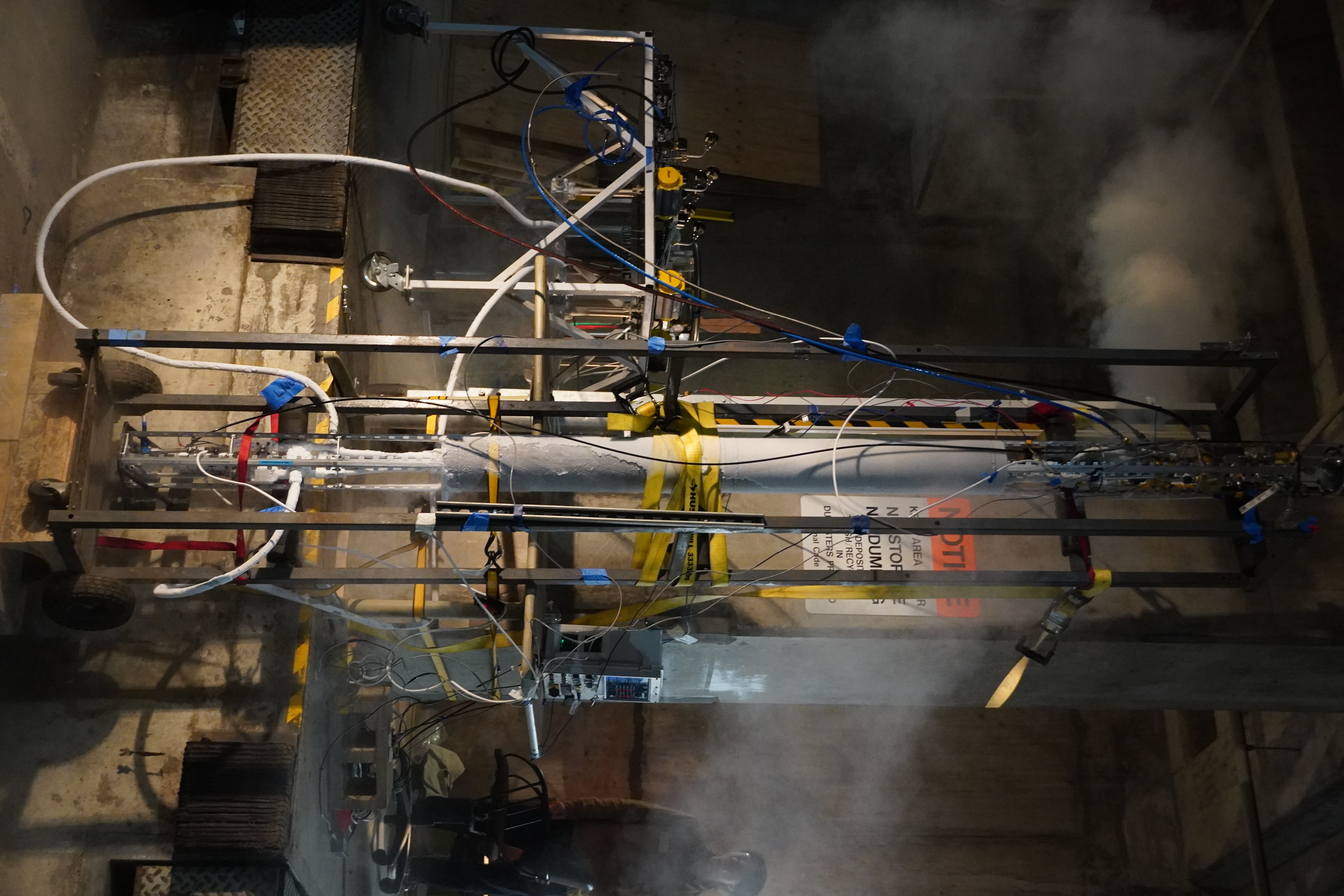
2. Integrated structures and fluids systems prepared for testing, ground support equipment table in background
Operations
In addition to my contributions to the structural design and manufacturing of the vehicle, I am also assisting integration and testing operations of the fluids and propulsion teams.
This includes multiple cyrogenic cold flows and static fires of the engine and vehicle. These tests give us valuable information and help characterize the system so that we can adjust our designs and optimize performance.
1. Vehicle venting during cold flow
2. Vehicle upright for cold flow (click to show full vertical image)
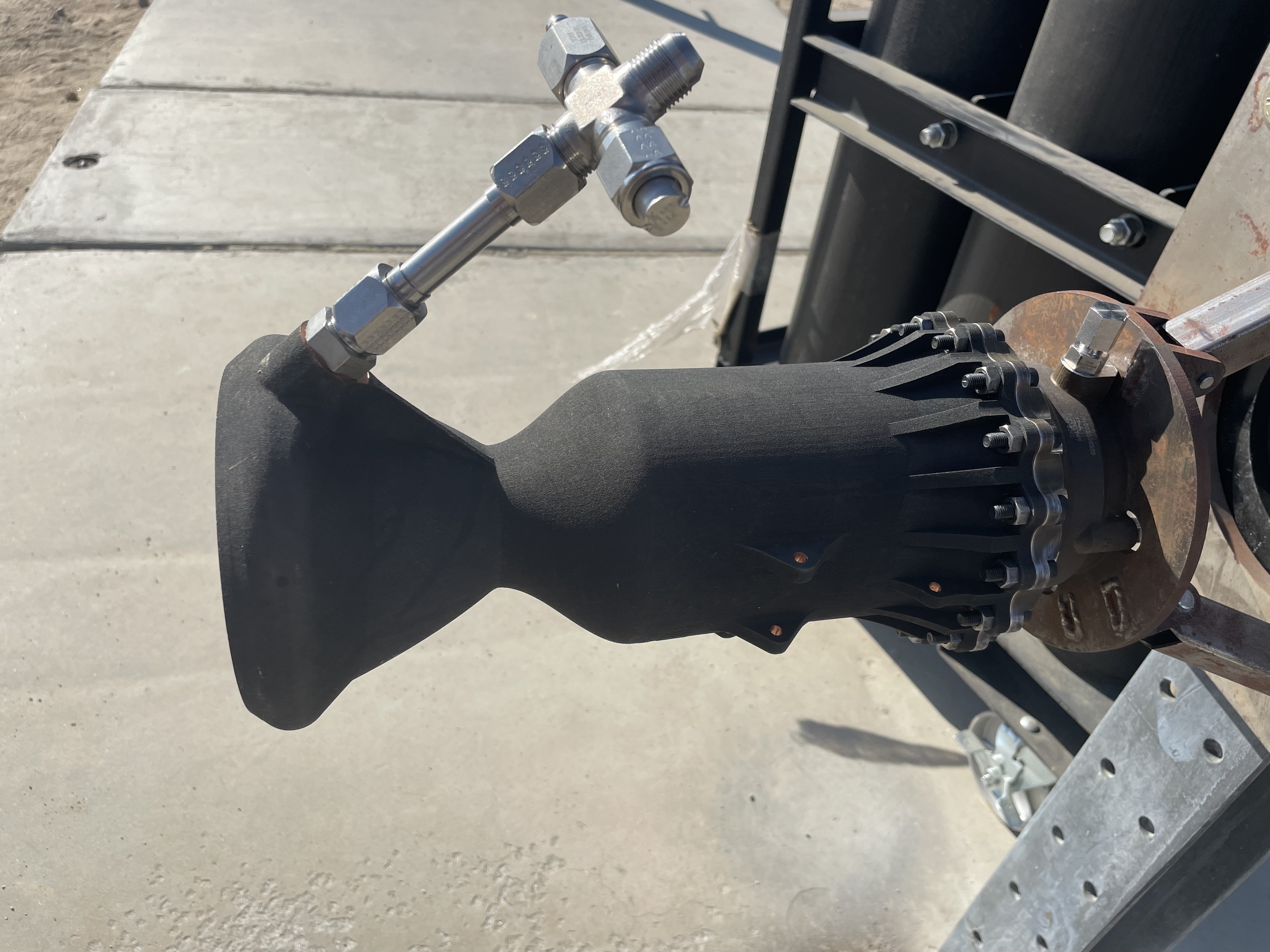
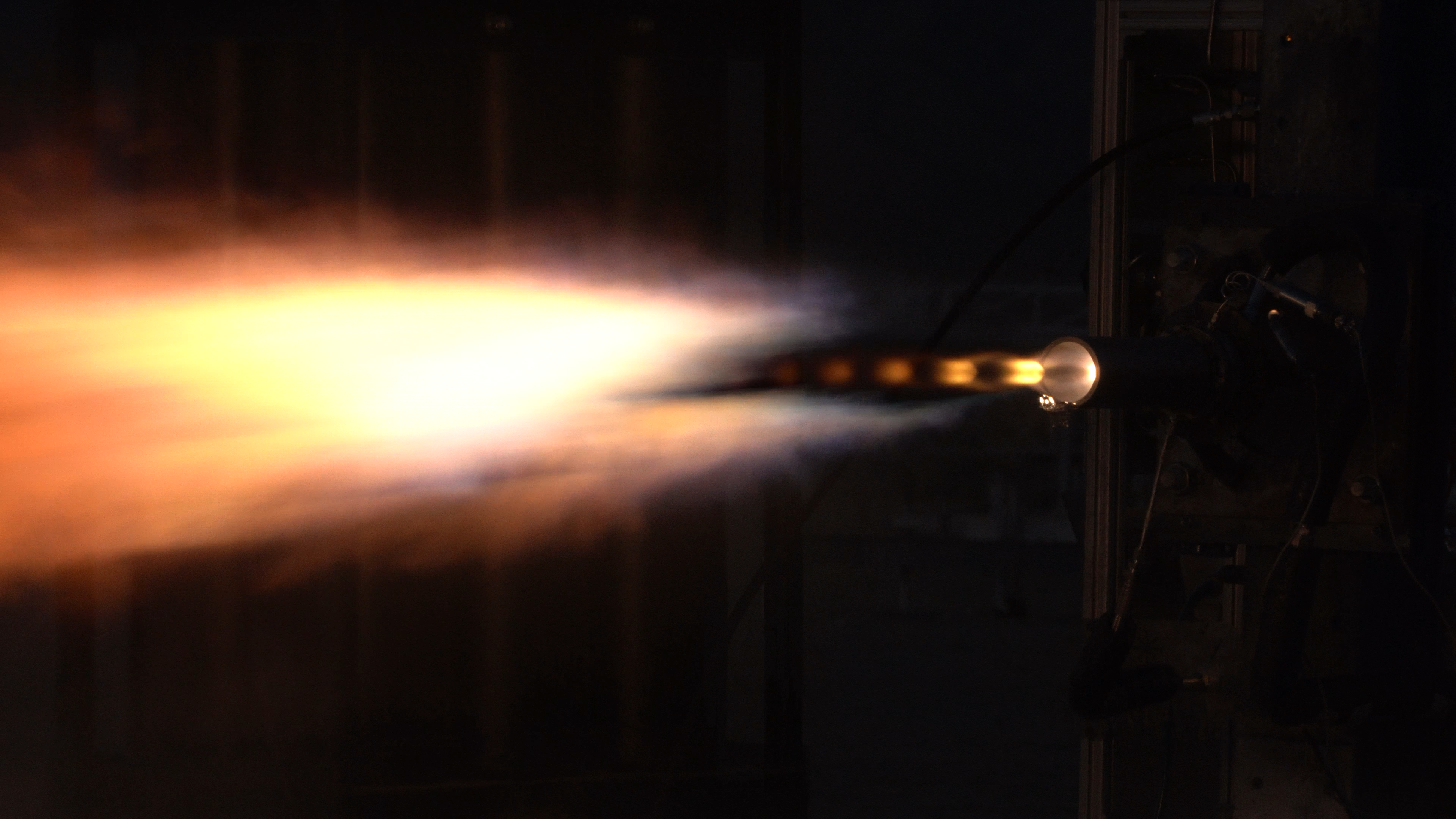
3. Nephas flight chamber on test stand
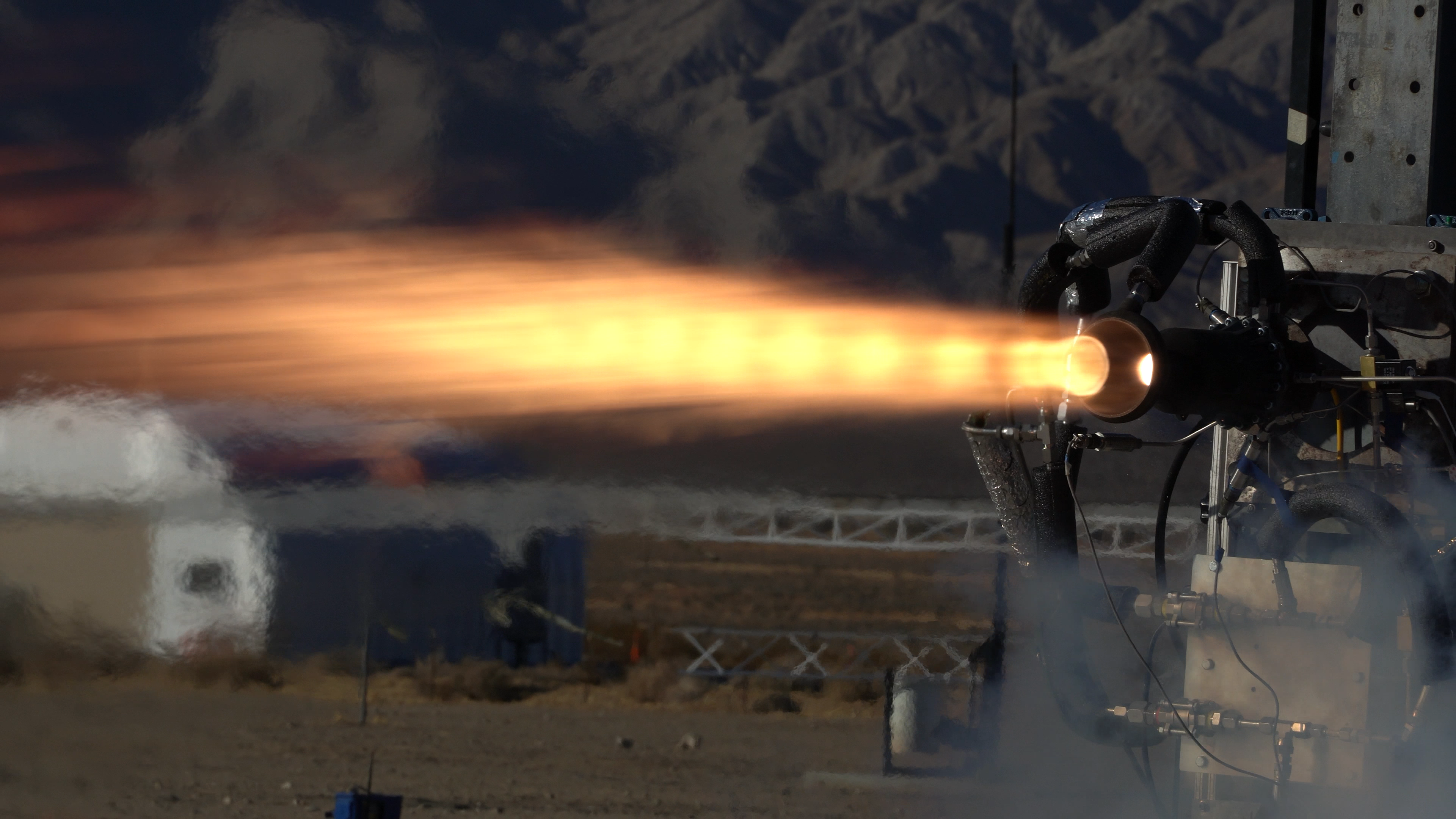
4. Nephas flight chamber static fire
5. Nephas flight chamber static fire video
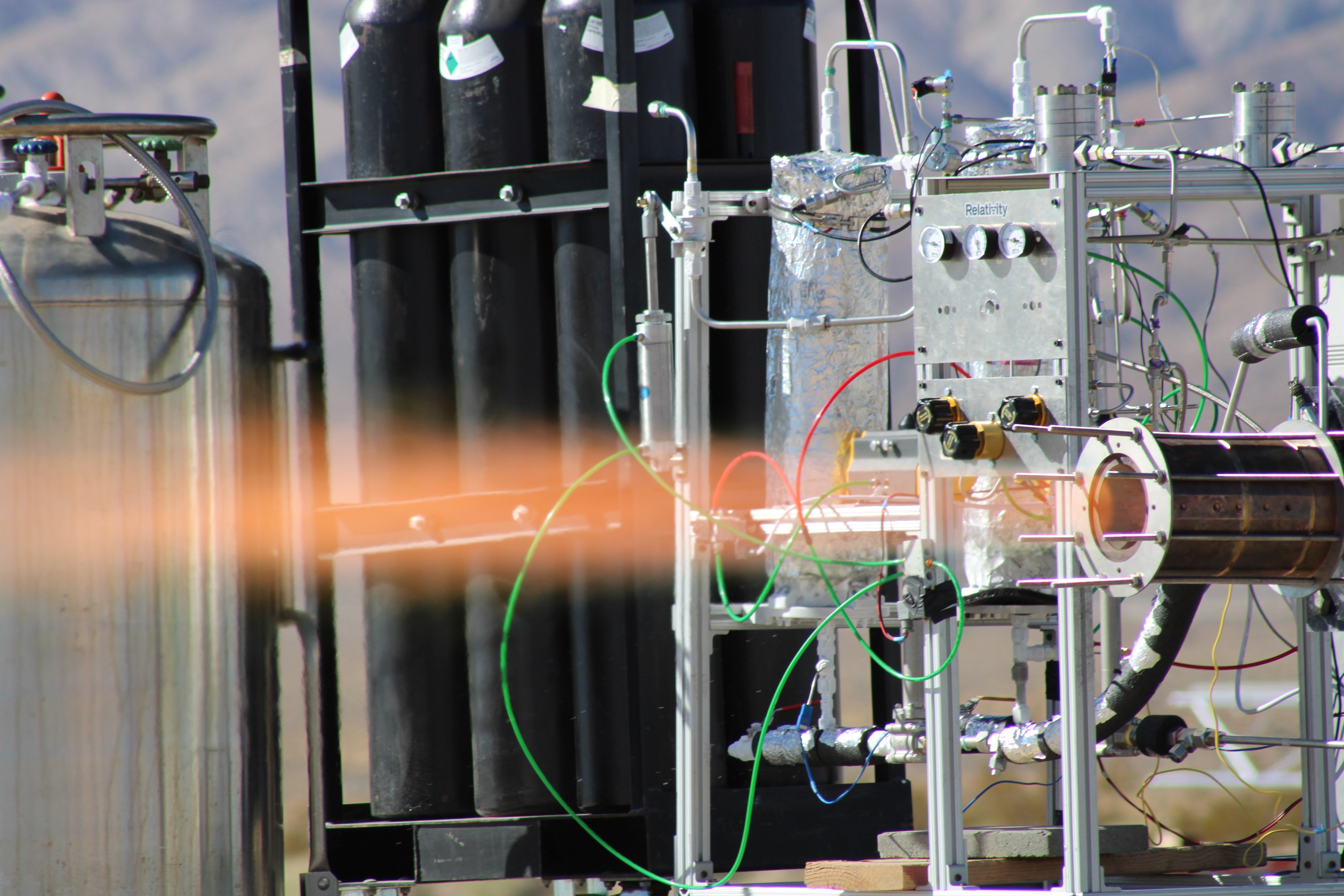
6. Nephas battleship chamber static fire
7. Nephas battleship chamber static fire video
8. Nephas battleship chamber static fire slow motion
9. Moonshine (engine for another vehicle) static fire
10. Moonshine static fire video
11. Moonshine static fire closeup video
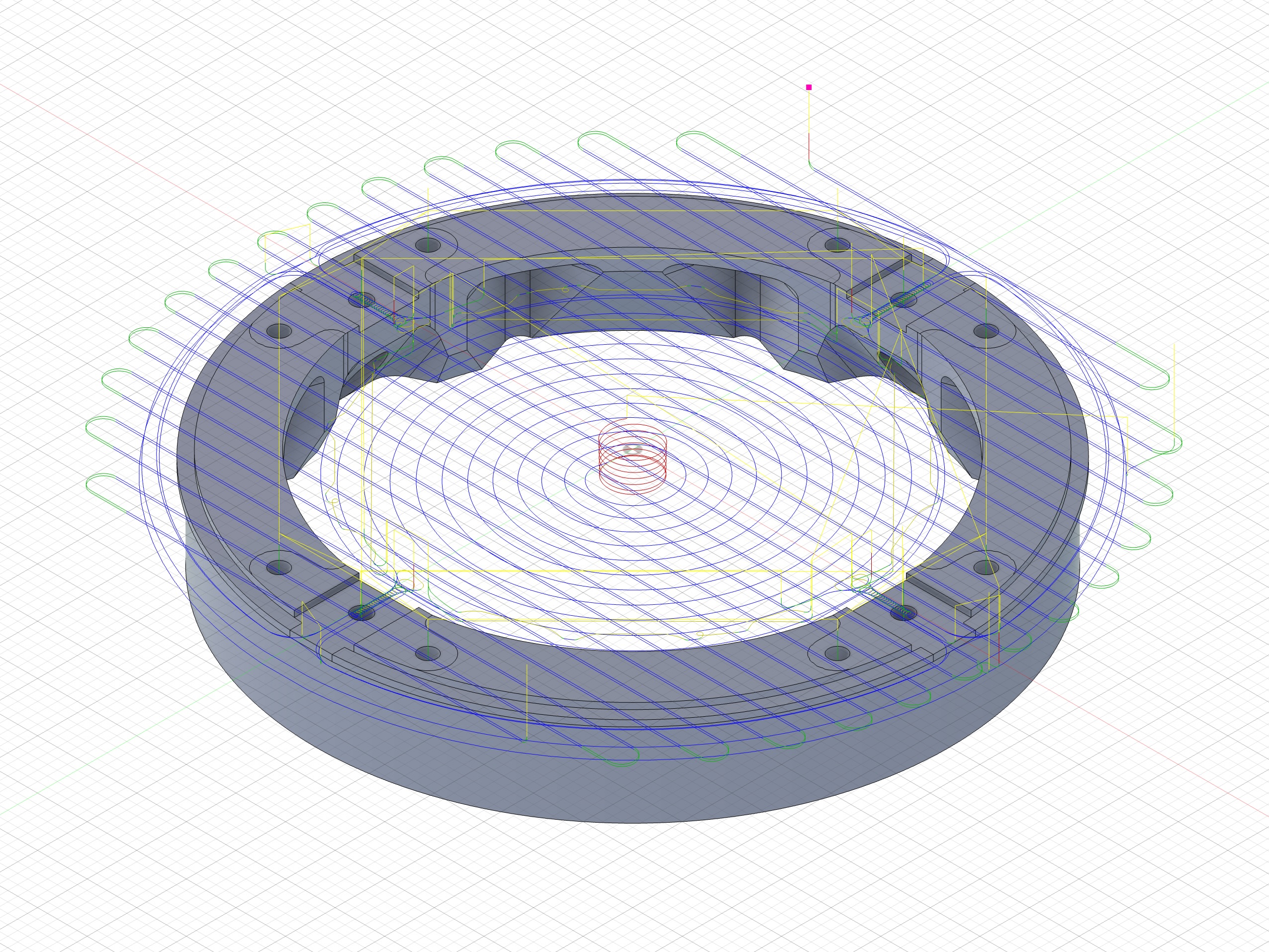
Coupler Ring
The coupler ring on Halya attaches two sections of the rocket: the aluminum frame of the pressurant section, and the composite tube housing the upper avionics and recovery bay.
As the responsible engineer for this component, I estimated the loads applied during launch and recovery, and then began performing component level FEA analysis in ANSYS Mechanical.
Based on the results of that analysis, I iterated the geometry in Solidworks, reinforcing high stress areas.
As I approached a final design, I ran higher fidelity assembly level simulations that included the bolted joints and surrounding components.
I continued iterating until the component achieved an acceptable safety margin with minimal weight.
Now, I am in the process of machining this component out of aluminum 7075.
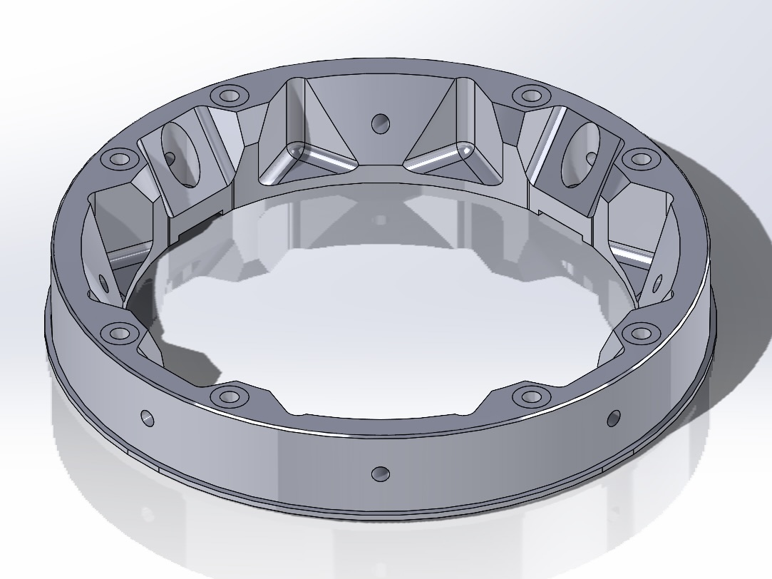
1. CAD design
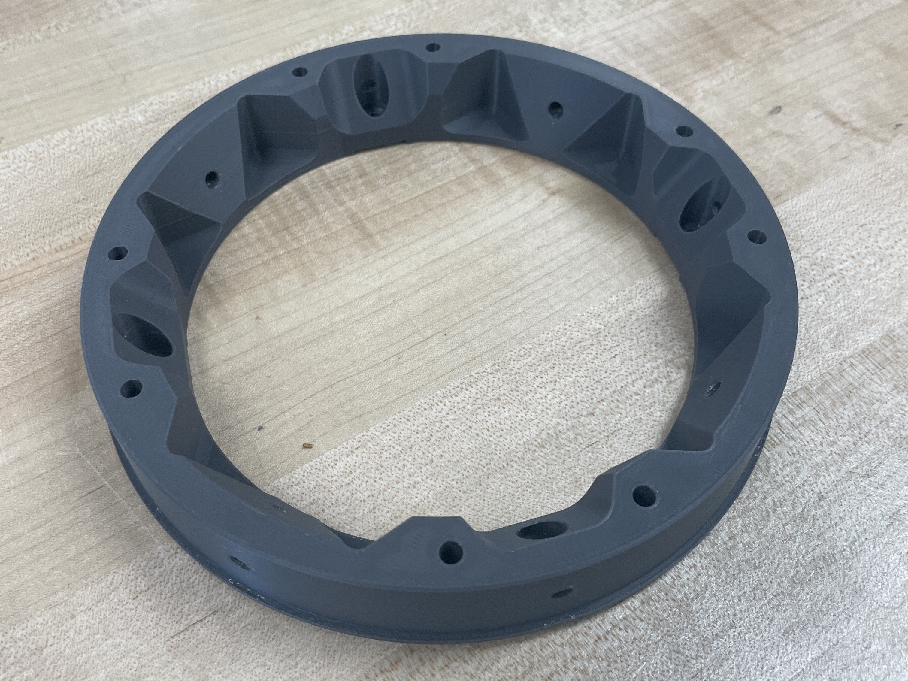
2. 3D printed prototype
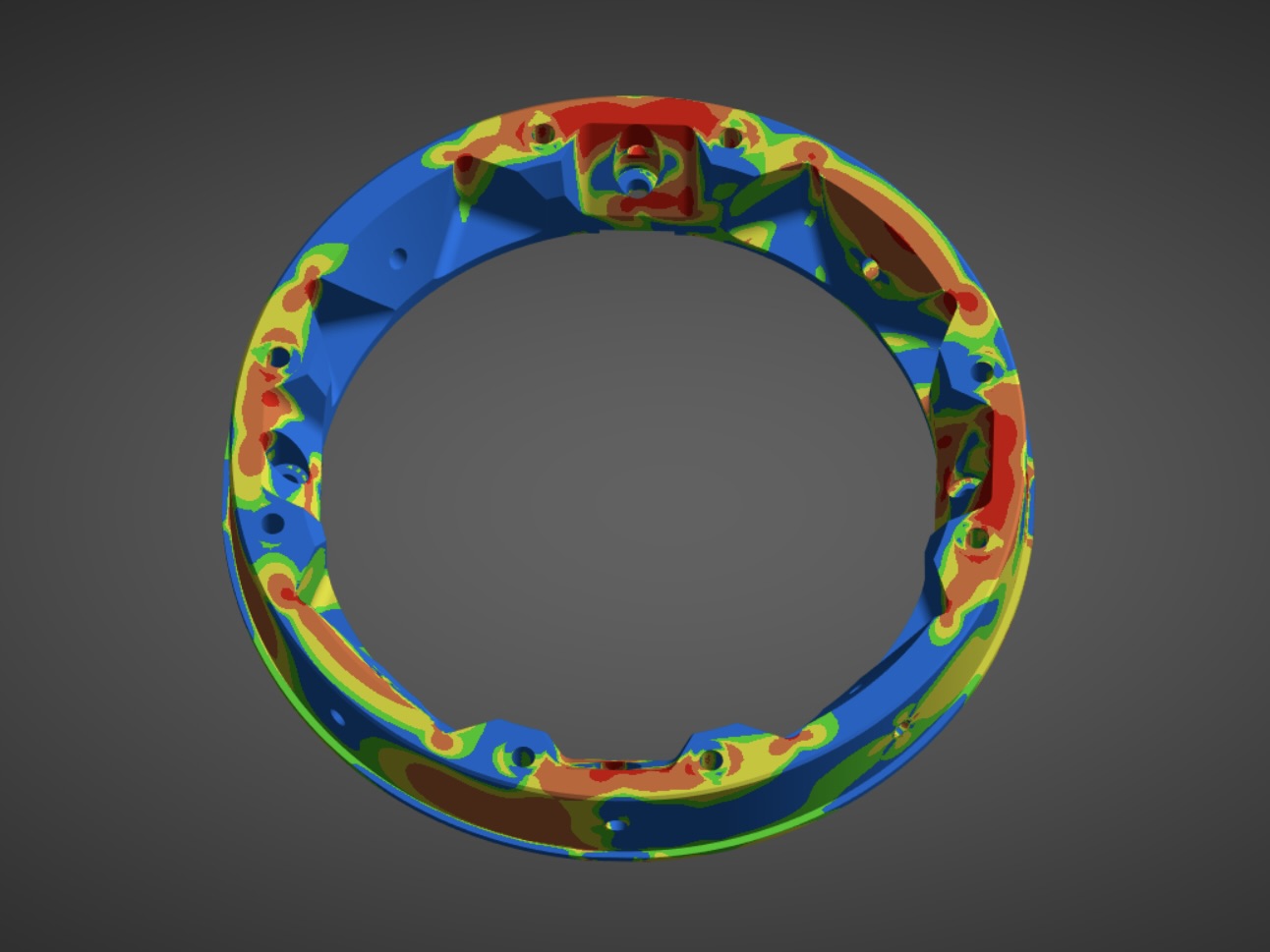
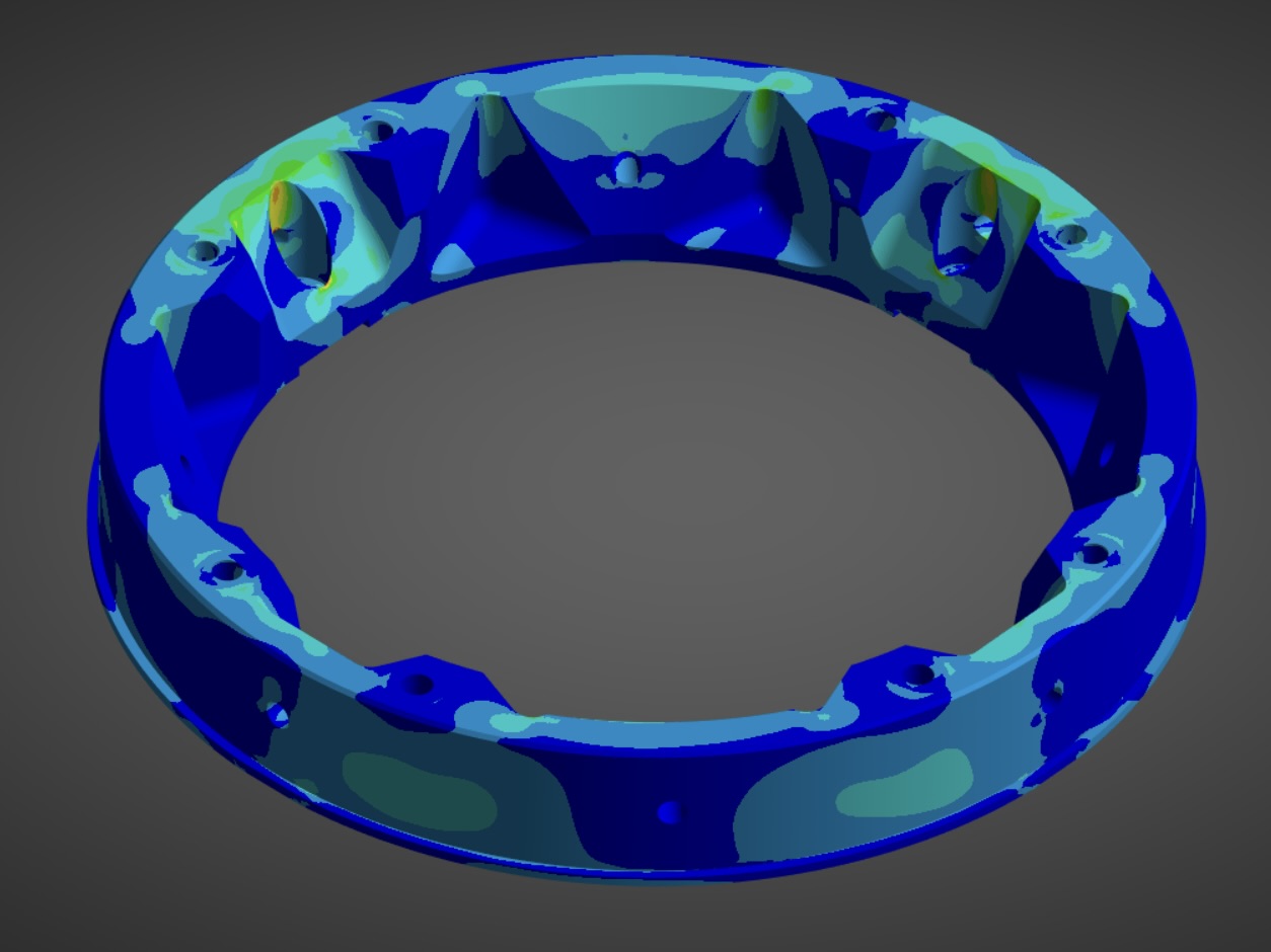
3. Safety margin, tensile yield
4. Von Mises stress distribution
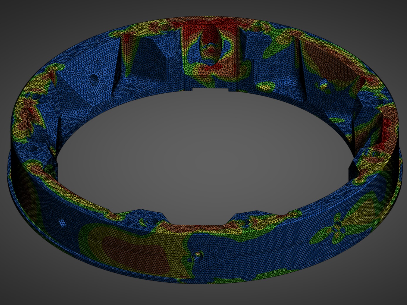
5. Safety margin, tensile ultimate, with mesh
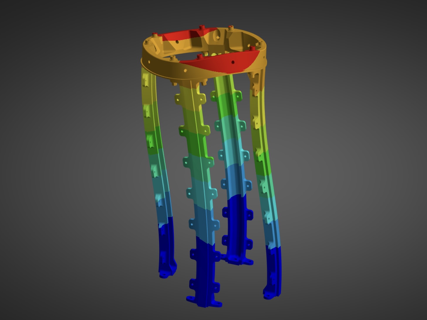
6. Assembly level deformation, exaggerated 20x
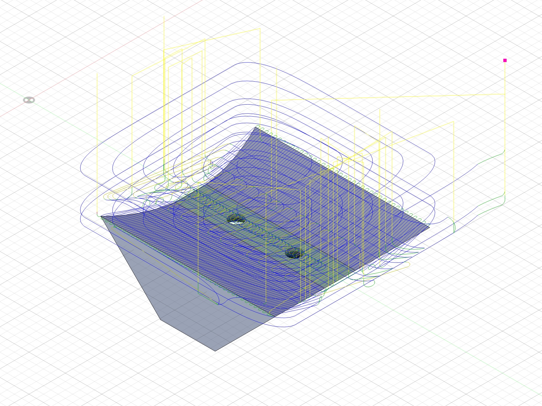
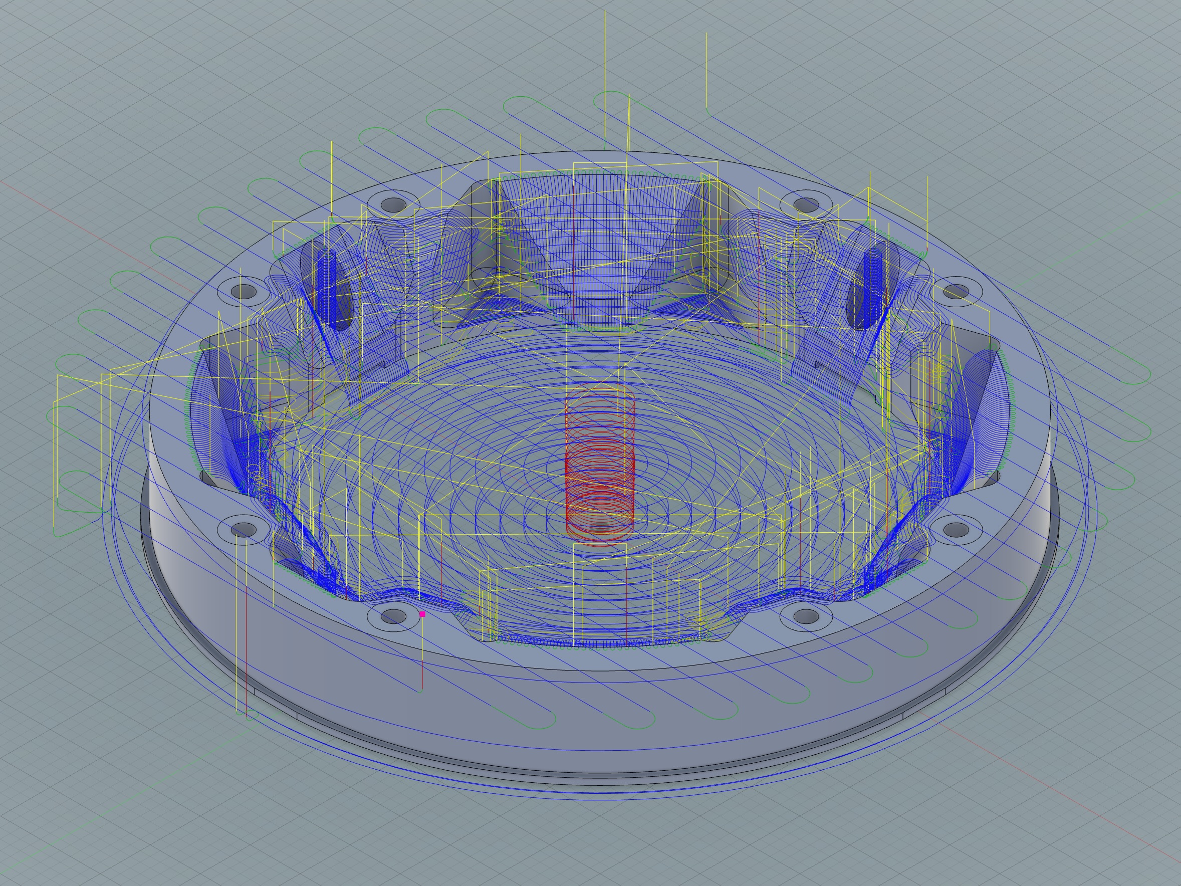
7,8. Tool paths
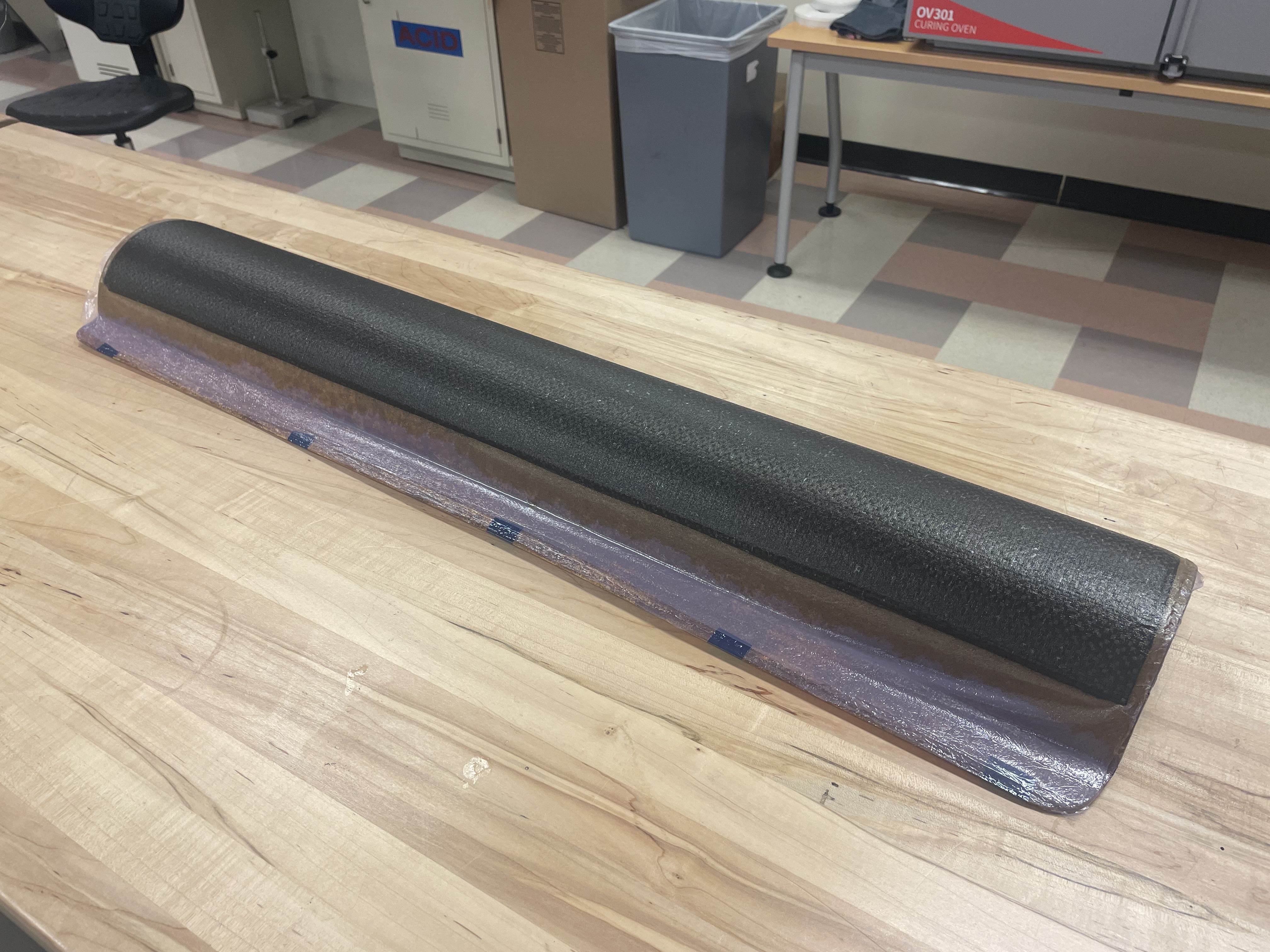
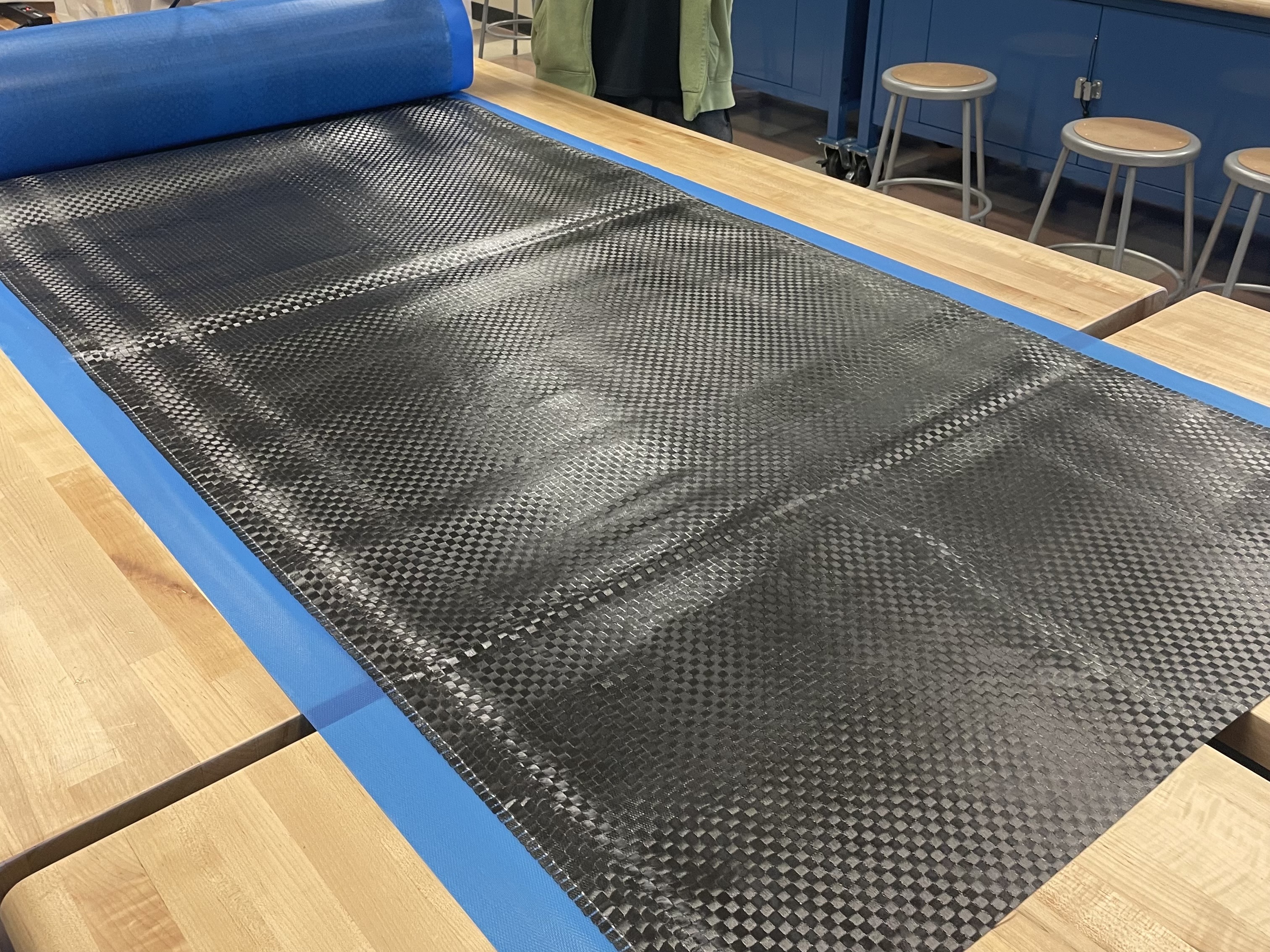
Composites
I was responsible for developing the manufacturing process for Halya's aeropanels, 3 foot long quarter cylinder panels that enclose the aluminum frame.
I first used a routed MDF mold and a fiberglass wet layup to manufacture an oven safe mold.
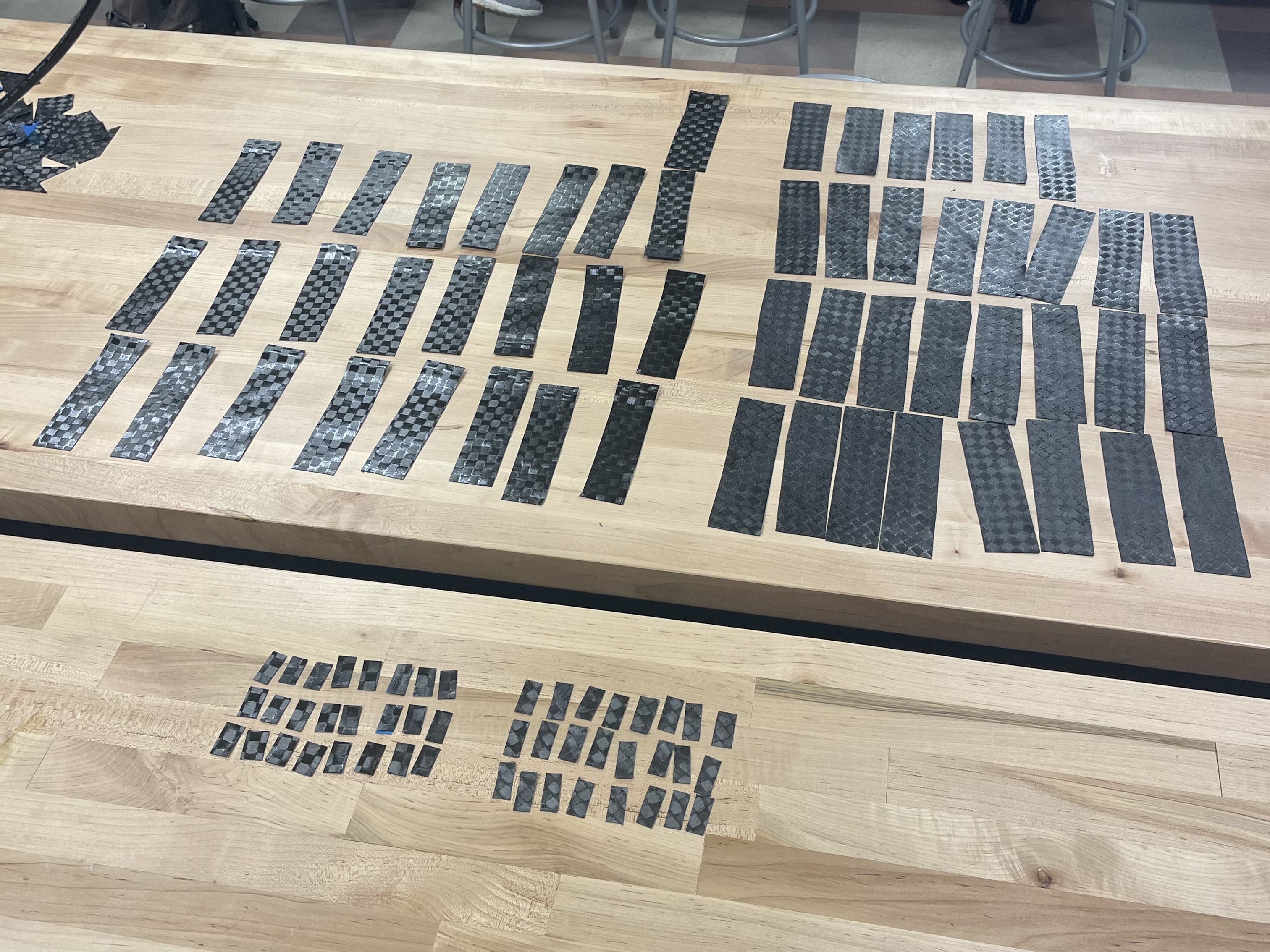
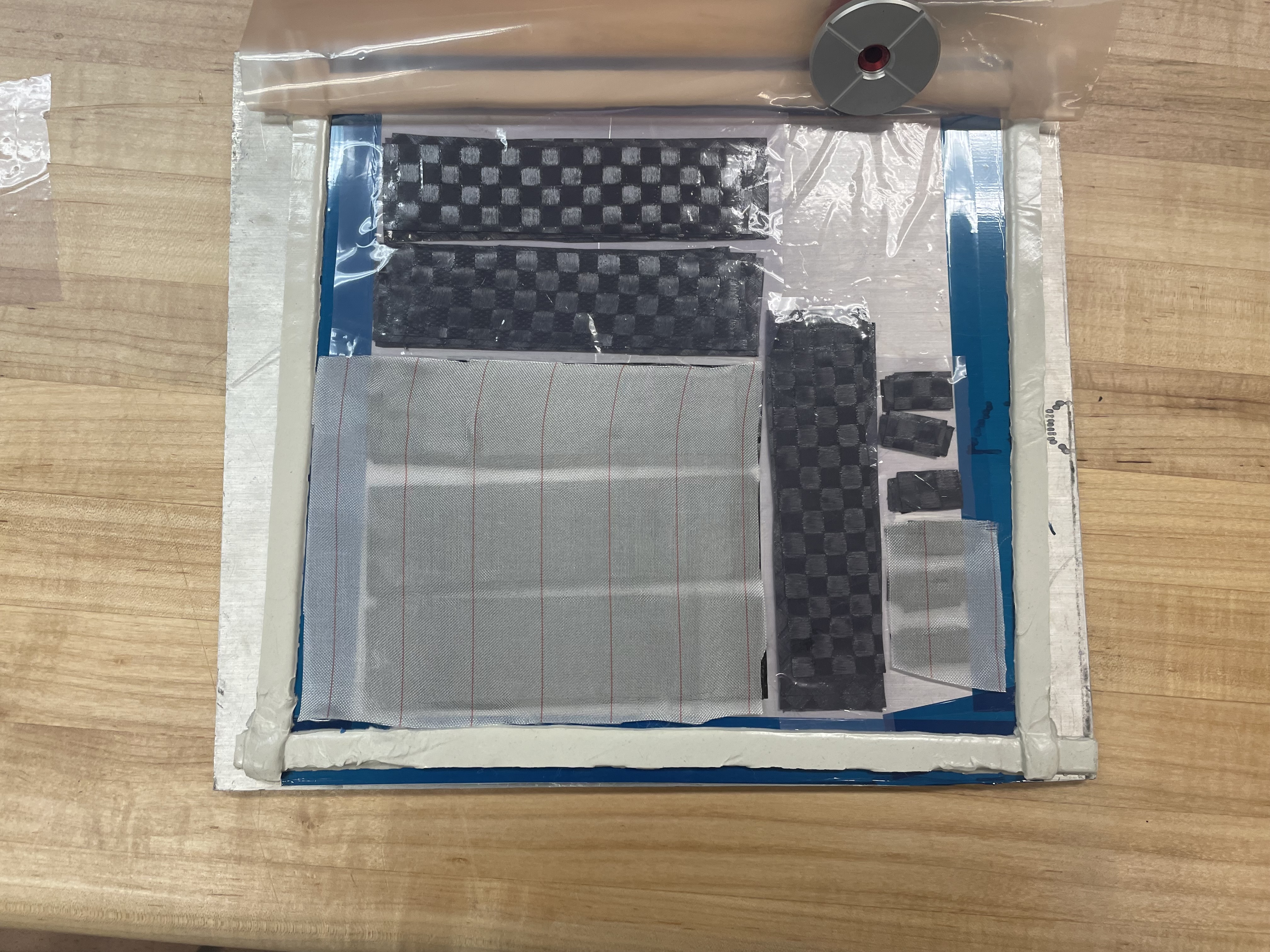
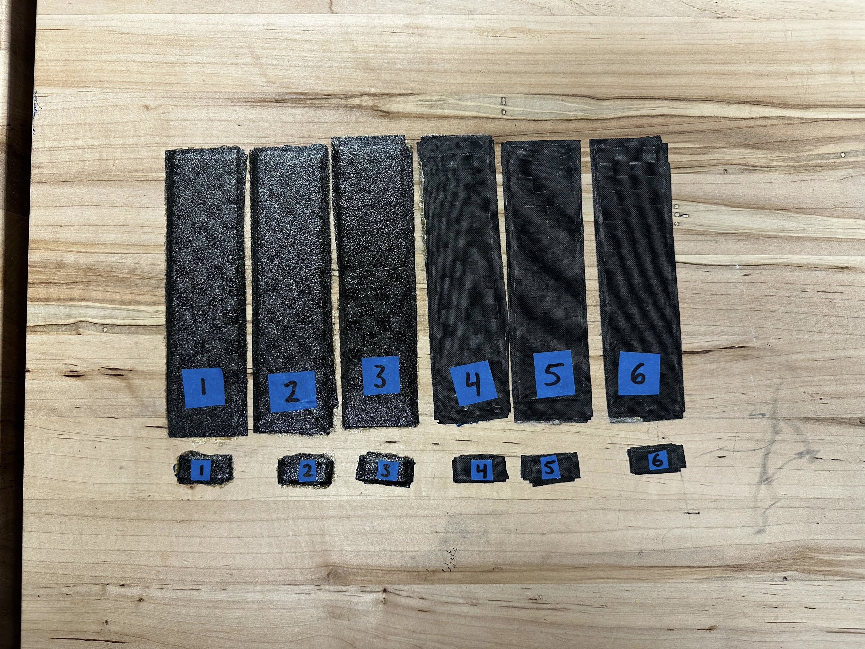
Then I manufactured ASTM tensile and SBS coupons for testing. These coupons were manufactured with varied processes, confirming the material properties and experimentally determining the optimal layup procedure.
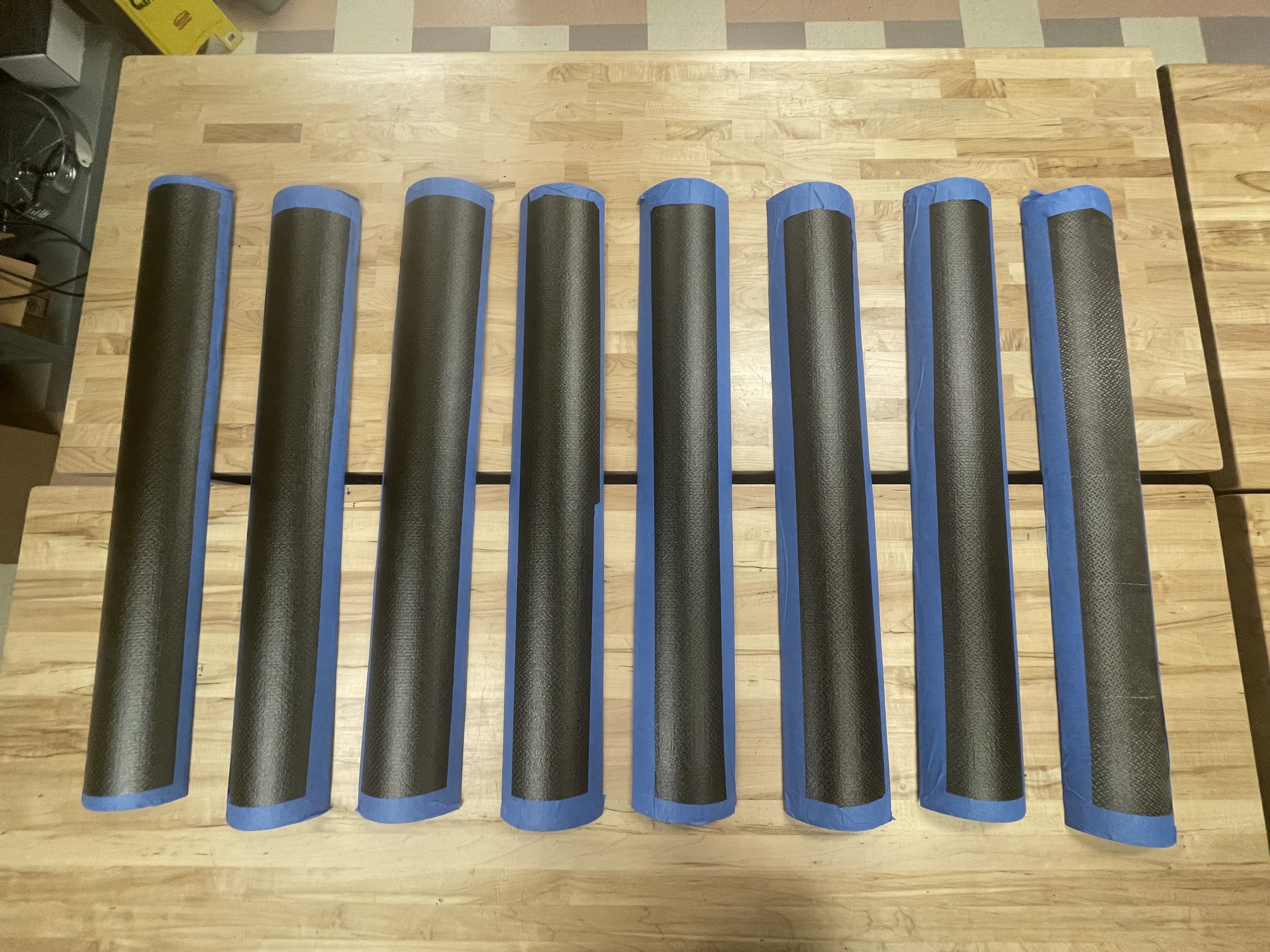
Following that, I manufactured a full set of 8 aeropanels.
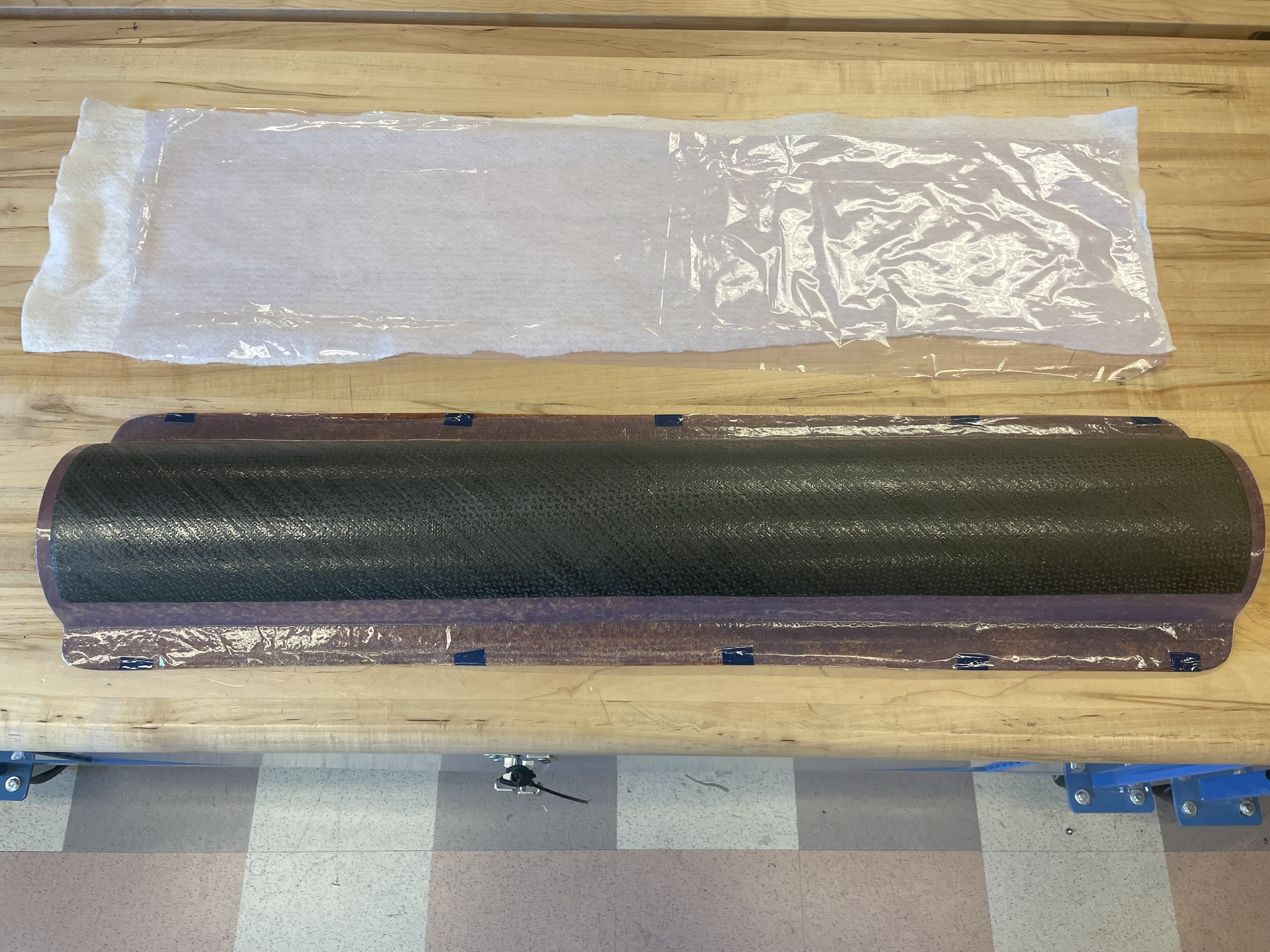
1. Cured aeropanel still on mold
2. 8 completed aeropanels
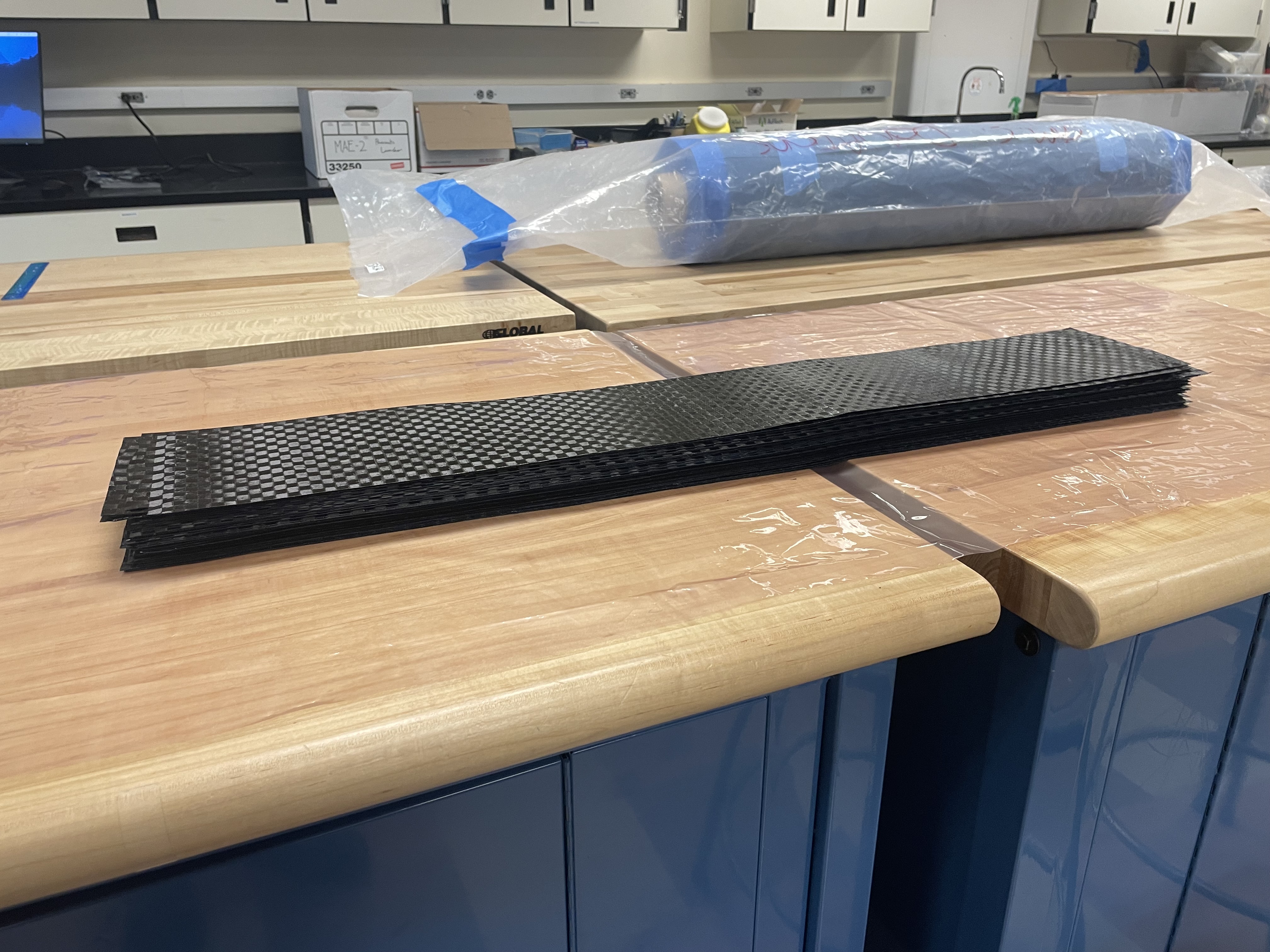
3. Prepared plys
4. Aeropanel layup in progress
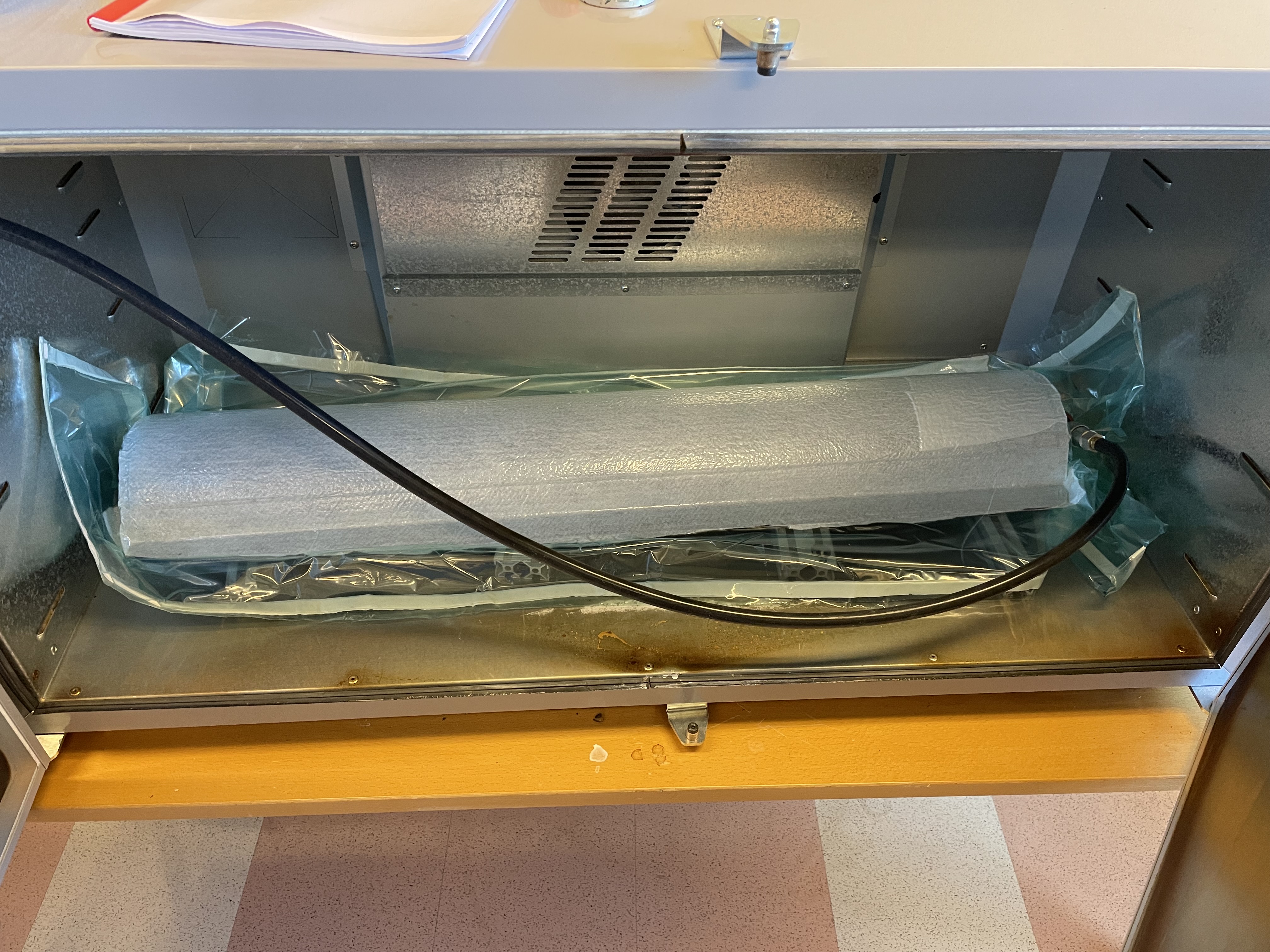
5. Aeropanel layup in vacuum bag, prior to cure
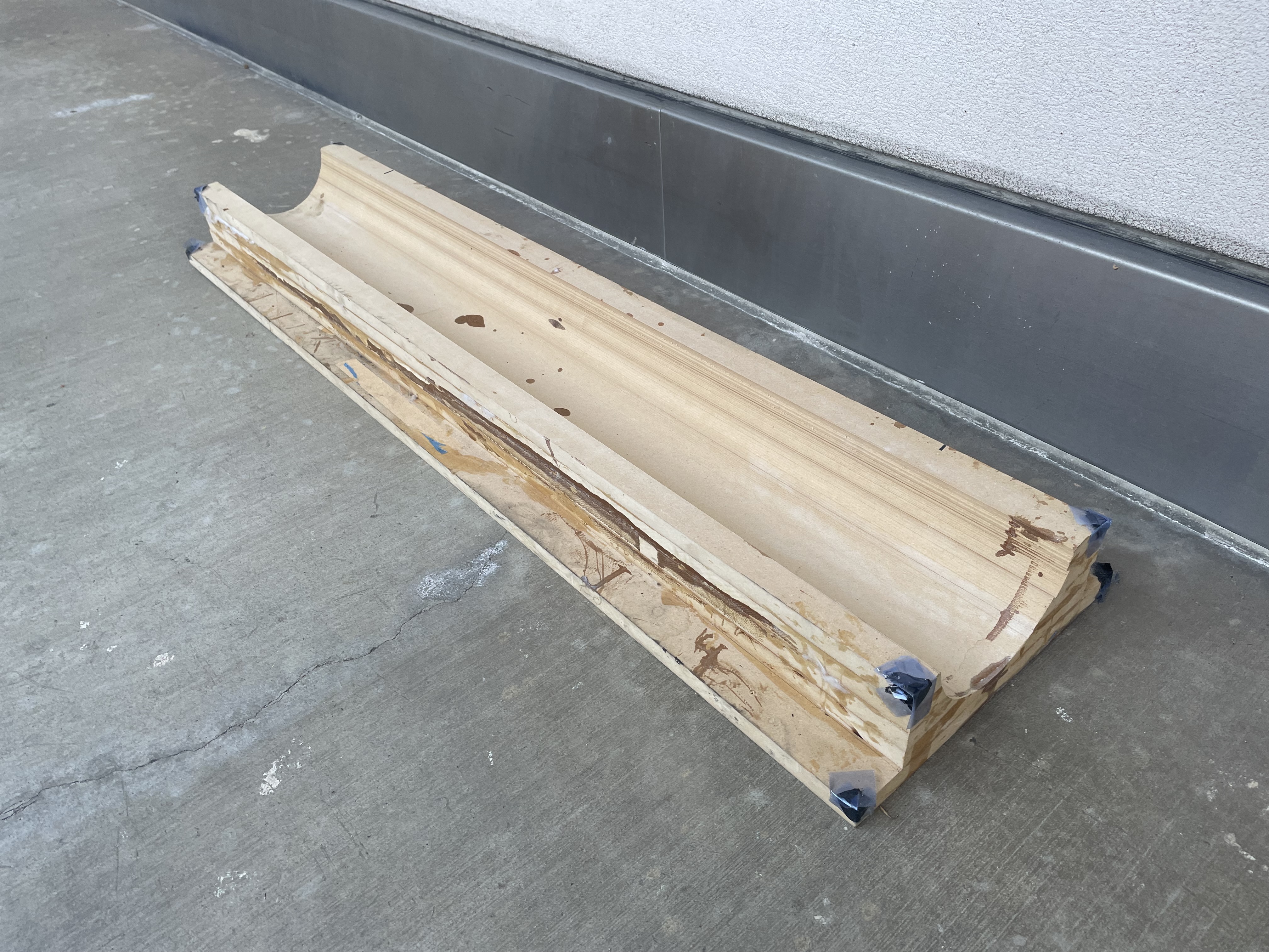
6. MDF positive mold
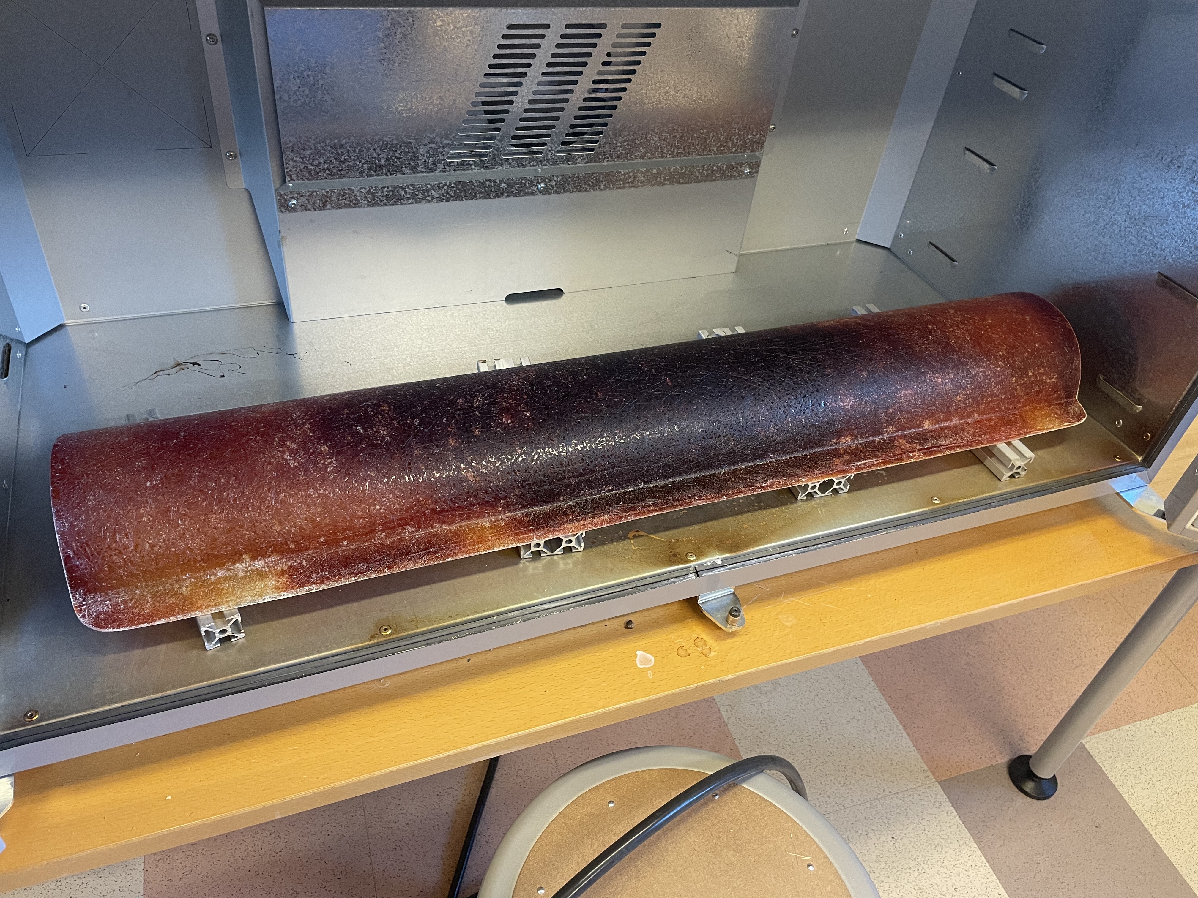
7. Fiberglass negative mold
8. Raw prepreg carbon fiber
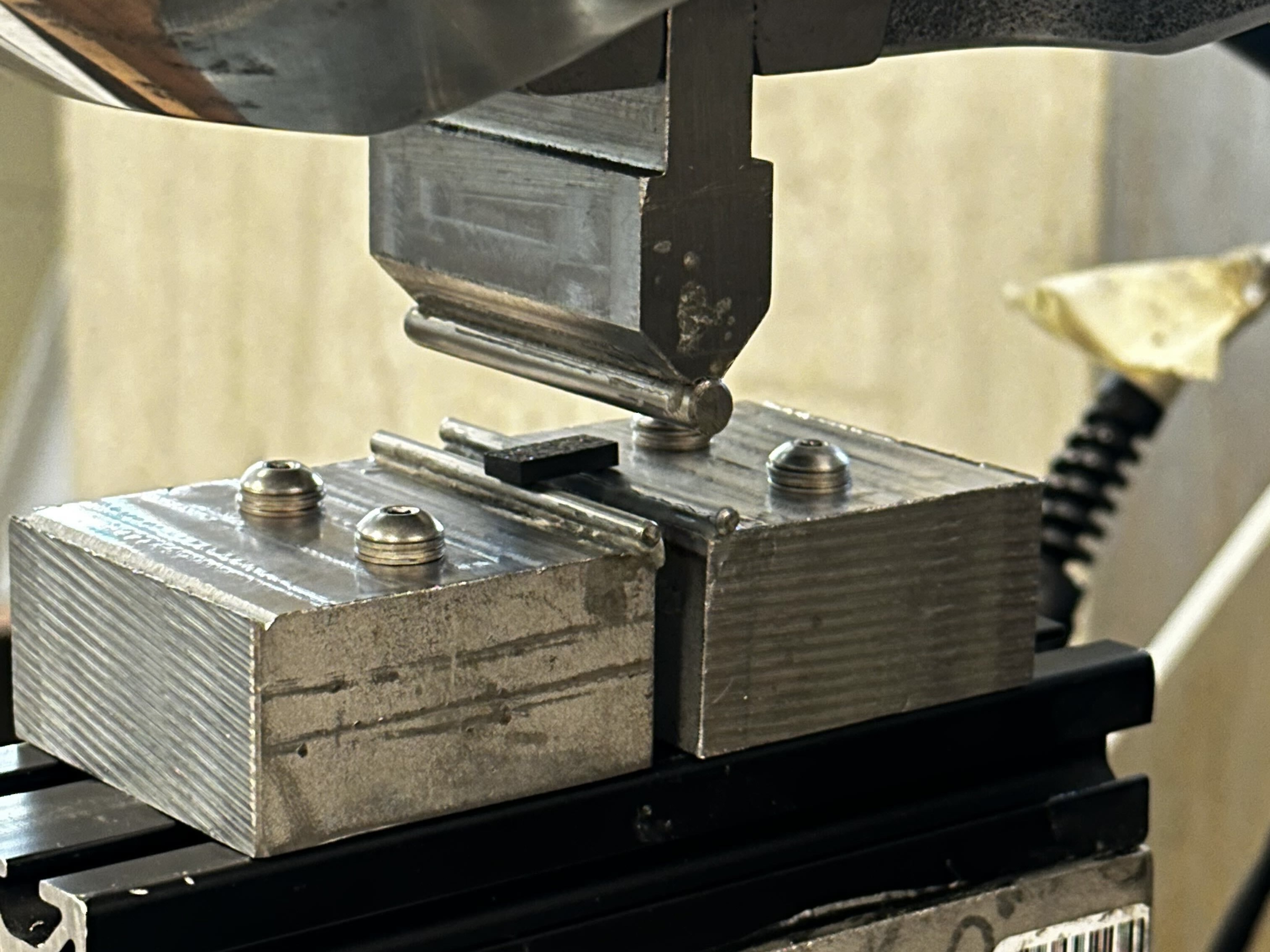
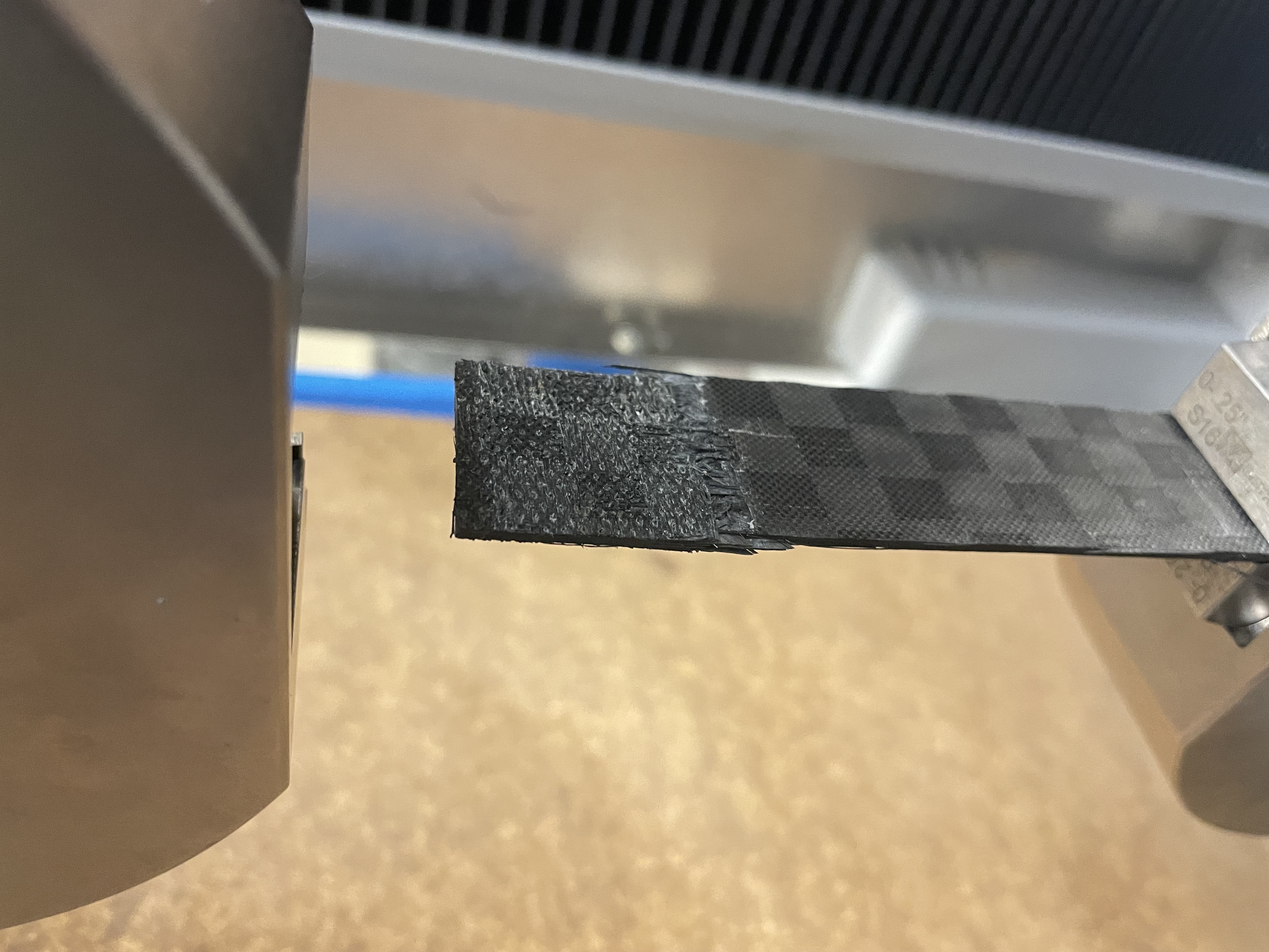
9,10,11. ASTM tensile and SBS coupon manufacturing
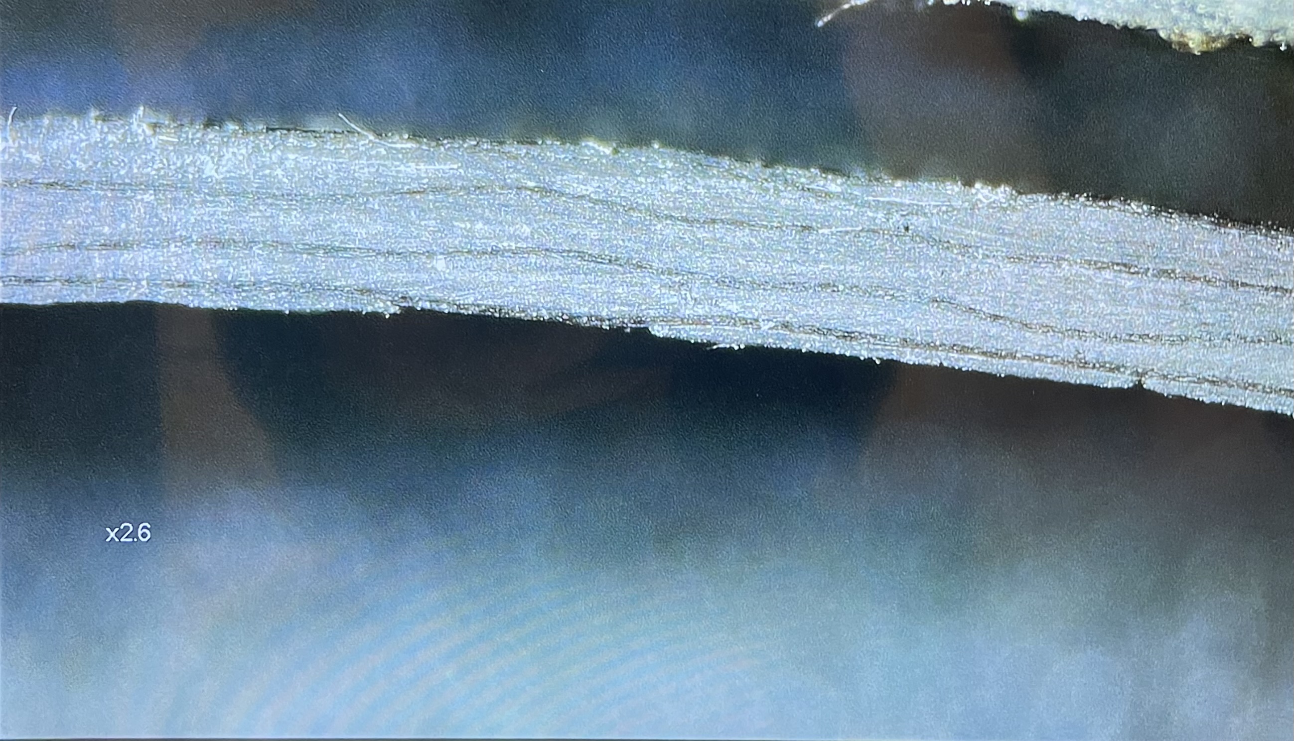
12,13,14. Laminate inspection and coupon testing
Launch Lugs
The launch lugs are attached to the outside of the vehicle and are responsible for guiding it along the launch rail during launch.
I was responsible for designing, analyzing, and machining these components.
I used ANSYS Mechanical for the FEA simulations and iterated the geometry in Solidworks, and then used a Haas VF-2 to machine the components out of aluminum 6061.
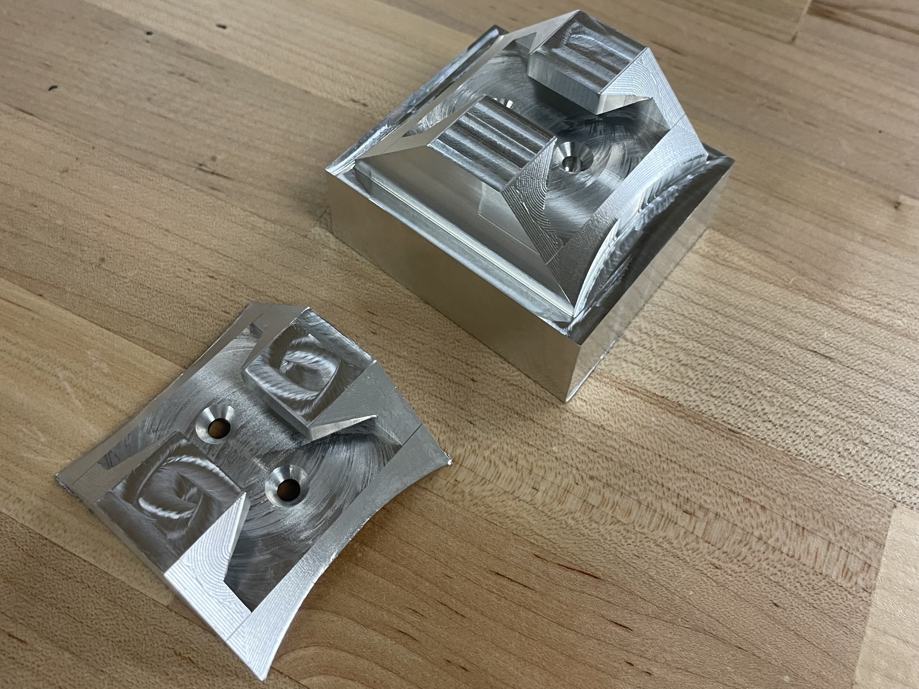
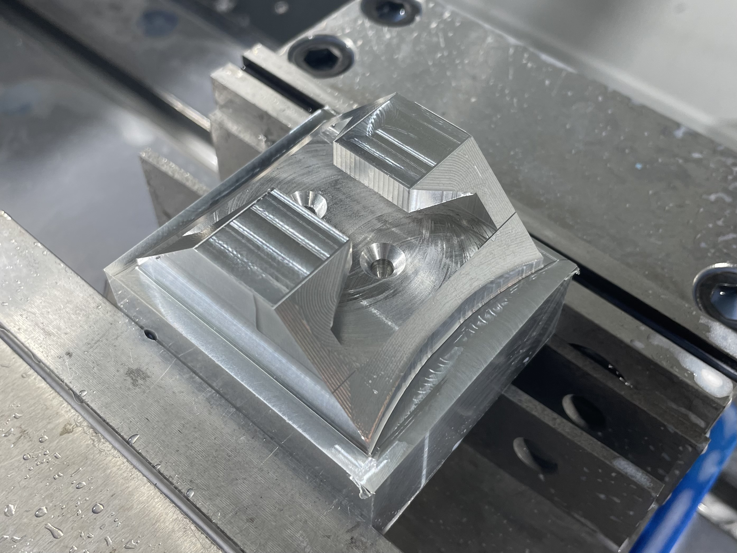
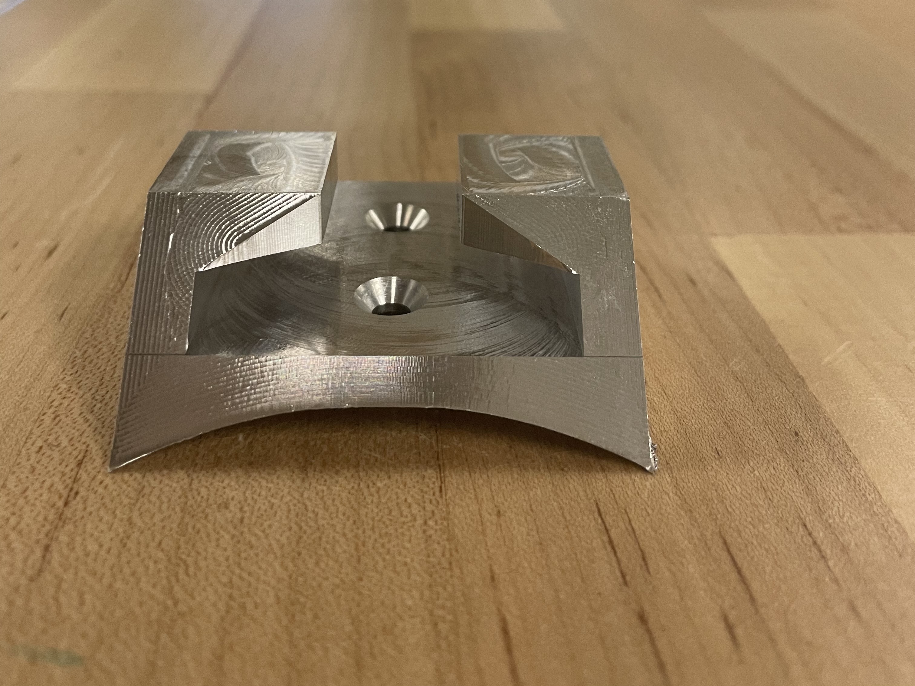
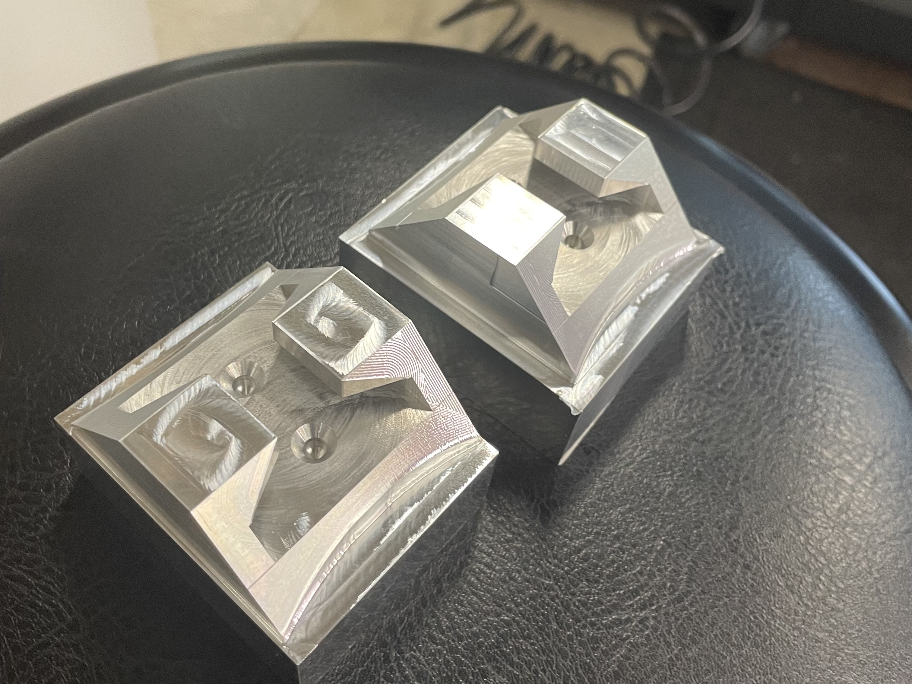
1. Two launch lugs, one complete and one partially machined
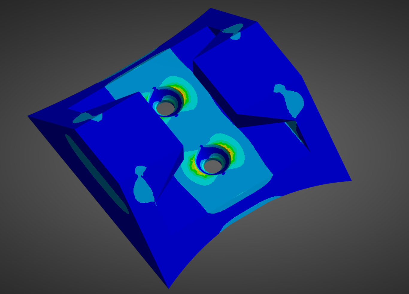
2. Von Mises stress distribution
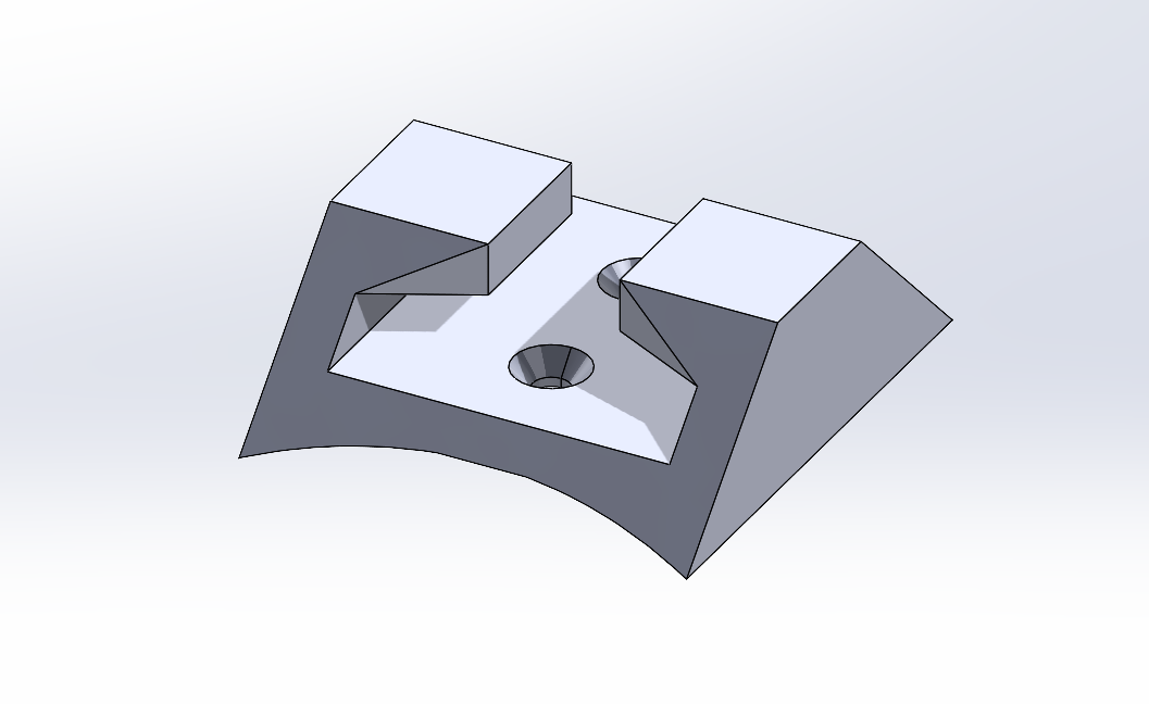
3. Launch lug CAD
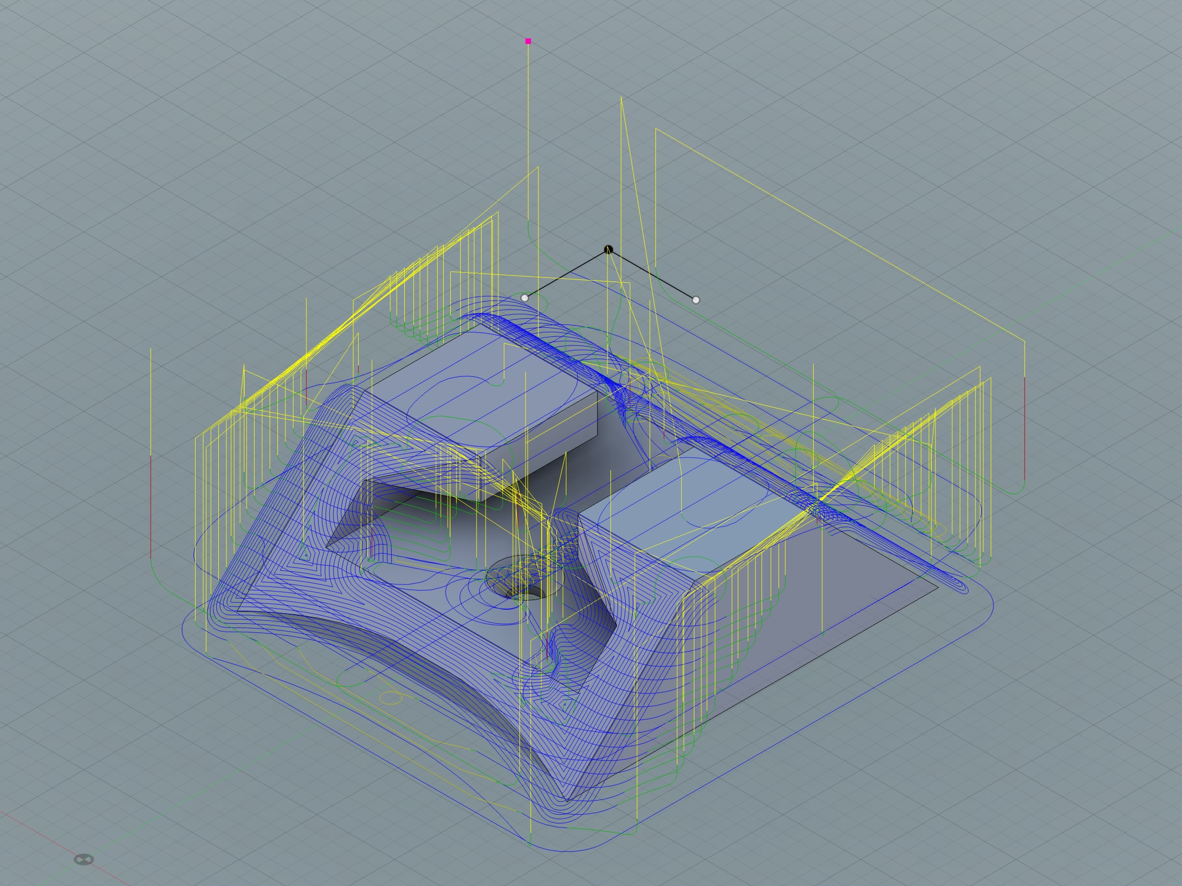
4,5. Machining tool paths
6,7,8. Machining process